Matrix stand
191 mm LED matrix · Raspberry Pi 5 · Adjustable camera
Printing, diffuser, fit and cable notes
Revision 7 targets no removable supports. The base has full-width sloped diffuser gussets. Print the new camera pad front-face-down as supplied; it is 11 mm high with a connected first layer. The small horizontal hinge holes need a bridge check in the final slicer preview. A brim is optional for adhesion.
The separate front slot accepts nominal 3 mm / ⅛-inch acrylic. Cut approximately 191 × 191 mm to match your measured display, deburr, and slide it down from above. The slot can stay empty. Test an acrylic scrap in the fit gauge before printing the base.
The sheet sits parallel to the panel with a nominal 6 mm minimum gap from its modeled face. Check the actual LED lenses clear it. Frosting and light blending are illustrative here; the optical result needs testing.
The hardware shapes are simplified references. Print the panel gauge and insert coupon first, then check the actual unpowered hardware against the full-size layout before printing the base.
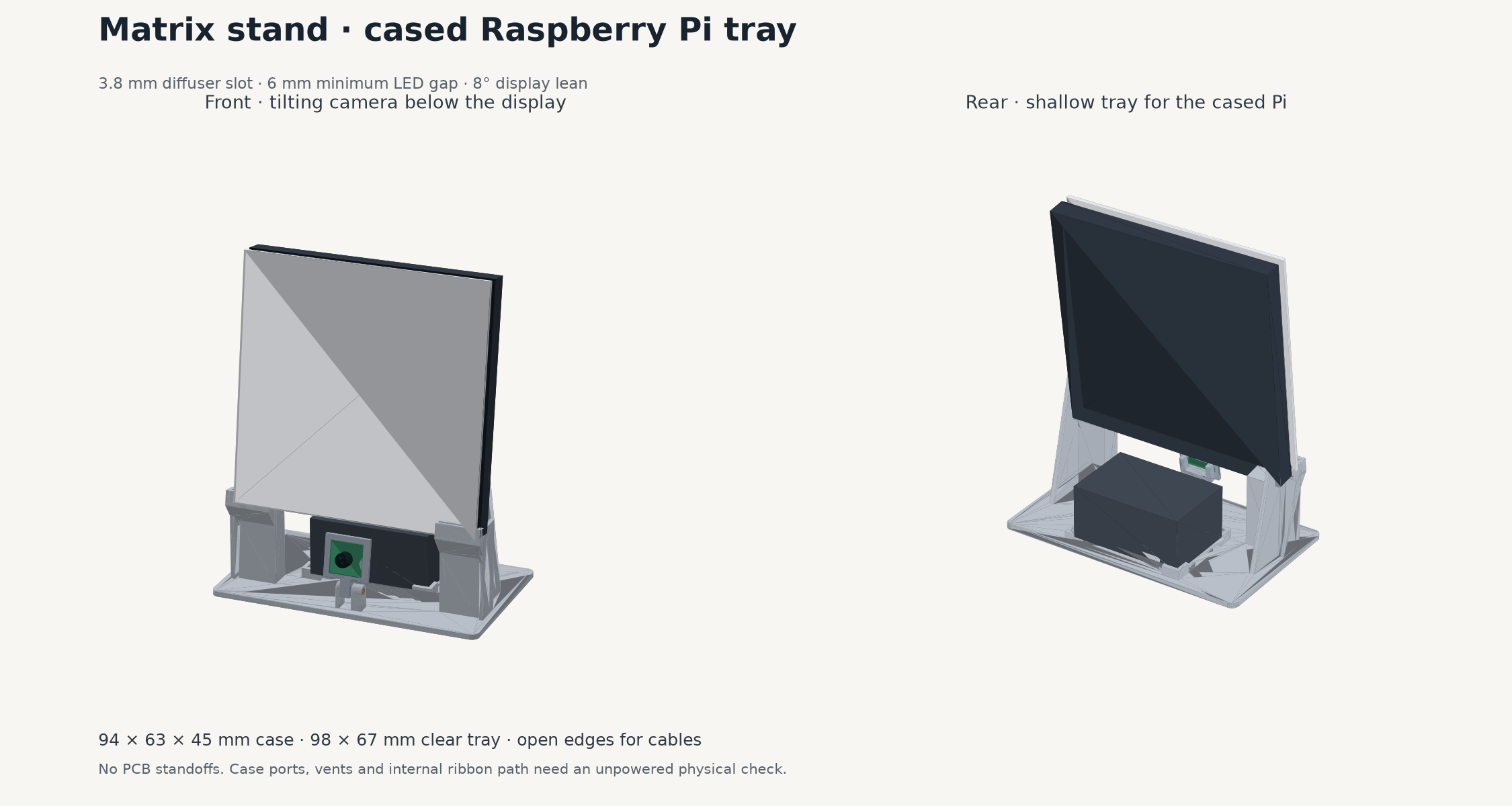
The case sits with its 94 mm side left to right. Keep the existing camera ribbon exit toward the front camera. A preliminary route budget is about 101 mm of the measured 135 mm cable, including 35 mm for bends, layout and an assumed internal case path. The actual case exit and internal route are unmeasured; check a relaxed loop through the camera’s tilt range before printing.
The Pi case rests on two low rails over a vented floor. Low corner rims locate it, with open edges for cables. Check the real case feet, ports and vents; the preview uses a plain outer envelope. Remove the hardware before carrying the stand.
CAD reference views